The parts change. The process mostly doesn’t.
That’s the useful thing about learning how to build a PC properly. You’re not memorizing a shopping list that becomes obsolete the second a new graphics card launches. You’re learning how to match hardware to a job, check compatibility, assemble everything without mangling expensive pins, and figure out what went wrong if the first press of the power button produces absolutely nothing.
We’ll work from choosing components through assembly, troubleshooting, and the BIOS settings you should check before booting your operating system. Consumer desktops, tiny gaming rigs, and enormous workstations have their differences, but the underlying habits carry across all of them.
What You'll Learn
- Choose components around your workload, budget, and physical compatibility rather than specifications alone.
- Assemble and test the core hardware before installing it inside the case.
- Prevent common failures by checking standoffs, connector alignment, cooling mounts, and cable seating.
- Verify temperatures, memory, storage, and firmware settings before starting your operating system installer.
Table of Contents
- Step 1: Pick Parts for the Computer You Actually Need
- Step 2: Prepare Your Workspace and Tools
- Step 3: Install the CPU on the Motherboard
- Step 4: Install the Memory
- Step 5: Install the M.2 SSD
- Step 6: Mount the CPU Cooler
- Step 7: Test the Core Components Before Installing Them in the Case
- Step 8: Prepare the Case and Check Every Standoff
- Step 9: Install the Motherboard and Connect Front I/O
- Step 10: Install SATA SSDs and Hard Drives
- Step 11: Install Case Fans and Radiators
- Step 12: Install the Power Supply and Finish Power Wiring
- Step 13: Install the Graphics Card and Other Expansion Cards
- Step 14: Finish Cable Management
- Step 15: Power On and Troubleshoot Methodically
- Configure the BIOS and Boot Your Operating System
Step 1: Pick Parts for the Computer You Actually Need
Before comparing processors, answer one question: What am I going to do with this computer?
A gaming PC, a music workstation, and a home file server can all use familiar-looking components while needing very different things. Spending more doesn’t fix spending on the wrong hardware.
Gaming: Choose the Experience Before the Graphics Card
For a gaming build, the graphics card will usually deserve a large chunk of the budget, with the CPU following behind. But “gaming” is not a sufficiently specific requirement.
- Visually rich RPGs and exploration games: A high-resolution display, preferably with good HDR, can matter more than premium competitive peripherals. A controller might suit some games better than a fancy keyboard and mouse.
- Competitive shooters: Prioritize a responsive mouse and a high refresh rate display. Giving up some resolution or color accuracy can make sense when every millisecond matters.
- Streaming or recording: Leave additional CPU headroom and pay attention to the GPU’s hardware video encoder.
CPU core requirements also vary by game. Matching the core count of a contemporary console can be a rough starting point for longevity, and adding two to four cores can provide headroom for recording or streaming. Treat that as a starting point, not a substitute for benchmarks in the games and software you actually use.
Content Creation: Your Application Gets a Vote
“Creator PC” is another label that hides a lot of different requirements.
- Digital art: A drawing tablet may do more for your workflow than an expensive GPU.
- Music production: Large sample libraries and instrument patches can eat enormous amounts of RAM.
- Video editing: Plan for a capable GPU, plenty of memory, and a frankly unreasonable amount of fast storage if you work with high-quality footage.
- 3D modeling and rendering: Both CPU and GPU performance matter. Hardware ray tracing can be particularly useful for interactive previews and prototyping.
- Engineering: Validated professional hardware and software compatibility may be worth more than the highest consumer benchmark score.
- Programming: Frequent compilation can benefit from a powerful, highly threaded CPU and enough RAM to keep everything moving.
- Writing: A good keyboard and a decent display or two may be the most important purchases. Not every job requires a monster graphics card.
NAS and Home Servers: Define the Storage Workload
A basic file server can run on relatively modest hardware. The requirements change when you demand high throughput, lots of drives, or additional services.
- Cold storage: Backups, media archives, and other infrequently changed files usually favor capacity over speed.
- Warm storage: Frequently updated documents and photos call for a balance of capacity and responsiveness.
- Hot storage: Footage ingest and network boot workloads can justify much faster storage and a larger budget.
Also account for the work happening around the storage. A Plex server that transcodes media needs more processing power than a box that merely hands out files. Larger storage configurations can add CPU demands too. Motherboard connectivity, case drive mounts, and, in specialized applications, redundant power supplies become important considerations.
Choose a Form Factor You Can Live With
Small computers are cool. Discovering that your cooler, power supply, and graphics card cannot coexist inside one is less cool.
- ATX: The classic desktop format, commonly found in mid-tower and full-tower cases. It offers substantial expansion room and is a sensible starting point when you’re unsure.
- Micro-ATX: Smaller, with up to four expansion positions. That is enough for many builds, provided the particular board has your required connections.
- Mini-ITX and DTX: Compact options with one and two expansion positions respectively. They can pack in impressive features, but connectivity and physical clearances need more attention.
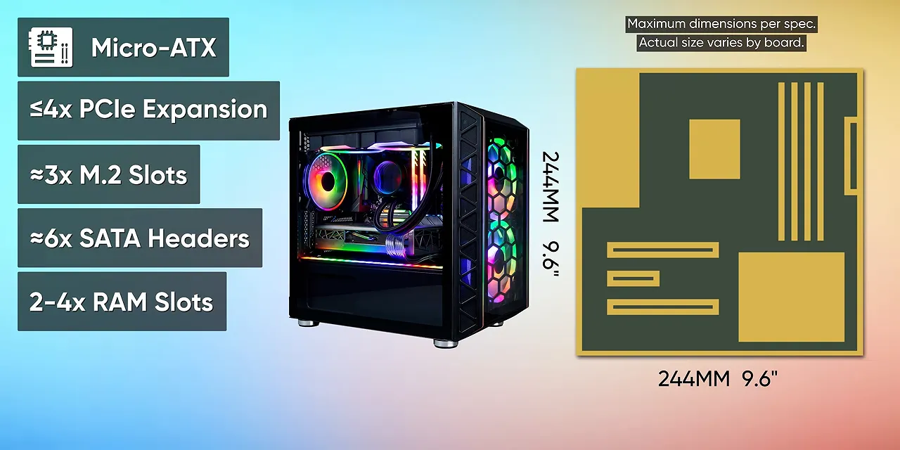
Larger cases often support smaller motherboard formats, but confirm the manufacturer’s compatibility list rather than assuming. A DTX motherboard may fit a particular Mini-ITX case, or it may not.
Check graphics card length and thickness, CPU cooler height, radiator space, and PSU dimensions. A giant graphics card can work in some compact cases, but the case has to be designed for it. If your goal is the smallest possible machine, either get a larger build or two under your belt first or become extremely friendly with the documentation.
Set a Budget, Then Shop for Value
If your budget is somewhere between “less than I’d like” and “whatever I can scrape together,” used hardware deserves serious consideration.
Off-lease business desktops can be inexpensive starting points, with much of the assembly already handled. Previous-generation components can also deliver excellent value, particularly used. CPUs and other solid-state components have no moving parts, while worn fans or thermal compound can sometimes be replaced.
There are trade-offs. An older socket can limit future CPU upgrades, and an older GPU may miss newer software features or reach the end of driver support sooner.
The GTX 1080 Ti versus RTX 2080 transition is a useful historical example: the newer card’s headline features did not automatically make it the better purchase for every workload or price. Conversely, the silicon shortage showed how badly normal value assumptions can break when discontinued cards sell above their original prices. In a distorted market, waiting or buying a modest stopgap can be more sensible than paying anything demanded.
CPU: Use Reviews, Not Just GHz
I normally start a build around the CPU and GPU. They consume much of the budget and narrow down everything else, from the motherboard platform to the case.
Clock frequency and cache are not reliable performance comparisons across architectures or generations. Read benchmarks that resemble your workload.
Specifications become more useful within a closely related product family. Consider the historical Core i9-11900K and Core i7-11700K: both offered eight cores and 16 threads, while their maximum advertised turbo clocks were 5.3 GHz and 5.0 GHz. That roughly 6% clock difference was a reason to question a price premium of more than $100, not proof of a universal 6% performance gap.
Beyond raw processing speed, consider:
- Whether you need integrated graphics.
- The number and generation of PCI Express lanes.
- Heat output and the noise required to cool it.
- Motherboard cost and upgrade options.
PCIe Gen 4 doubles the per-lane bandwidth of Gen 3, and Gen 5 doubles Gen 4. Whether that matters depends on the devices and workload, and the CPU, chipset, and board may not support the same speeds everywhere.
Product suffixes can also expose savings. Intel F-series desktop CPUs omit integrated graphics. In the Ryzen generations discussed here, AMD G-series processors combined integrated graphics with potentially attractive pricing relative to X-series models. Always check the exact processor rather than treating a suffix as a permanent promise about value or features.
GPU: Performance, Features, and Memory Quality
Graphics cards require the same discipline: read reviews. Comparing clock speeds or memory capacity alone is not enough.
Look for features that your applications can actually use, including hardware encoding, real-time ray tracing, NVIDIA DLSS, Blender’s OptiX rendering support, and AMD FidelityFX features. A capability that improves your everyday workflow can matter more than a small difference in conventional gaming performance.
Between otherwise equivalent cards, more video memory is generally preferable. The key word is equivalent. A low-end card with lots of slow memory can still perform terribly. Both the memory capacity and the memory subsystem matter.
Motherboard: Buy the Connections You Need
The biggest, most expensive motherboard is not automatically going to make your PC meaningfully faster.
Chipsets can restrict memory speeds, overclocking, PCIe bandwidth, and expansion. For example, AMD’s A520 platform lacks CPU overclocking support, while higher-tier platforms can provide more expansion options. PCIe lane splitting, or bifurcation, may matter for particular high-speed storage or expansion configurations, but support must be checked on the exact board.
For most builds, a well-reviewed midrange motherboard with the correct CPU support and all the slots, sockets, fan headers, and lighting connections you need is the path of least resistance. There is no shame in taking it.
Before buying, check the CPU support list and any required BIOS version, not just whether the socket physically matches.
RAM: Capacity, Speed, Timings, Channels, and Ranks
System memory is described primarily by three characteristics:
- Capacity: How much working data the system can hold.
- Data rate: How quickly data can transfer, commonly expressed in megatransfers per second, or MT/s.
- Timings: Delays associated with memory operations. Lower timing values are desirable when comparing otherwise equivalent configurations.
More is not unconditionally better. Larger capacities and additional modules put more strain on the CPU’s memory controller, potentially reducing the stable speed or requiring looser timings.
Platform behavior matters too. Ryzen 3000 and 5000 systems are historical examples where DDR4 around 3600 or 3800 MT/s can be attractive because of the relationship between memory speed and internal clocks. Beyond a useful operating point, lowering latency may help more than chasing a larger speed number.
Many enthusiast kits reach their advertised settings through memory overclocking. Check the CPU’s official memory specification and the motherboard’s support information rather than assuming every advertised kit speed is guaranteed.
Buy matched kits appropriate to the platform’s channel configuration. A dual-channel desktop normally benefits from a matched pair, while workstation platforms may have more channels.
Ranks are not the same thing as channels. A rank is a group of memory chips accessed together. Multiple ranks can improve performance by allowing the controller to interleave work. On a dual-channel board, two dual-rank modules or four single-rank modules can provide a similar rank arrangement, though four modules may be harder to run at high speeds. Labels such as 1R and 2R can help identify the organization.
ECC Memory: A Separate Compatibility Check
DDR5’s on-die error correction is not the same as full system-level ECC memory. On-die correction protects data within individual memory chips. Full ECC also provides protection for errors that can occur along the memory data path.
That makes proper ECC attractive for servers and workstations where stability and data integrity matter more than squeezing out the last bit of performance.
There are also different module types:
- UDIMM: Unbuffered memory, the type used by most consumer desktop platforms. UDIMMs can be ECC or non-ECC.
- RDIMM: Registered memory, which buffers command and address signals to reduce loading on the memory controller.
- LRDIMM: Load-reduced memory, which adds buffering to support very large memory configurations, with latency trade-offs.
These are not interchangeable. Consumer boards usually accept UDIMMs, and even server boards have specific restrictions. Check both CPU and motherboard support before ordering a bargain pile of server RAM that your computer cannot use.
Storage: SSD for Responsiveness, Hard Drives for Capacity
Use an SSD for the operating system and important applications at almost any budget. Mechanical hard drives remain useful for inexpensive bulk storage.
Keep the terminology straight:
- SATA: An interface used by hard drives and some SSDs.
- NVMe: A storage protocol commonly used by PCIe SSDs.
- M.2: A physical form factor, not a guarantee that a drive uses NVMe.
An M.2 slot may support SATA, NVMe, or both. Your motherboard manual tells you which, how many drives can be installed, and whether using one slot disables something else.
For SSD shopping, look beyond peak sequential speeds. Consider cache design, endurance ratings, warranty length, and reviews of actual performance. A DRAM cache is a useful feature to investigate rather than simply choosing the cheapest drive with a large speed number. And back up your data. A quality SSD is not a backup strategy.
For hard drives, compare capacity, cost per terabyte, RPM, cache, noise, and operating temperature. A 7200 RPM model can offer better mechanical performance, but it also tends to generate more heat and noise. If the SSD handles your demanding work, a slower bulk-storage drive may be perfectly adequate.
Cooling: Big Air Is Not a Consolation Prize
Custom liquid cooling can offer excellent performance and flexibility, but it rarely wins on cost versus performance. It is also a whole project of its own.
For liquid cooling, heat-transfer surface area matters enormously. More useful cold-plate surface and more radiator area help move heat out of the processor and into the air. Extra radiator capacity can also let fans run slower.
Do not casually mix copper and aluminum in the same coolant loop. Galvanic corrosion can turn an expensive cooling project into an expensive lesson. Choose compatible wetted materials rather than relying on a bottle of coolant to rescue a bad combination.
AIO liquid coolers are simpler and less expensive than custom loops. A 240 mm radiator can suit many CPUs, while more demanding combinations may warrant 280 mm or 360 mm units. Match the cooler to the actual processor and workload rather than treating radiator size as a universal guarantee.
For most people, a good tower air cooler offers excellent performance with less complexity and fewer failure points. Some people think large heatsinks are ugly. Those people are wrong. But they are heavy, so account for that when transporting the PC.
If your CPU includes a suitable stock cooler, it may be enough. An upgrade is often about reducing temperature and noise rather than making the machine function at all.
Thermal Compound: Keep It Simple
Ordinary thermal paste from a reputable manufacturer is fine for most builds. Check whether it is electrically conductive instead of assuming.
Liquid metal is a different proposition. It conducts electricity and can react destructively with aluminum. Products of this type require compatible contact surfaces, such as copper or nickel-plated cooler bases, and much greater care. Traditional nonconductive paste is the much less exciting option, which is precisely why it is a good default.
Thermal pads also need to be appropriate for the processor, correctly sized, and handled according to their instructions.
Power Supply: This Is Not Where You Gamble
An efficiency badge is not a complete assessment of power supply quality. An 80 PLUS rating tells you about efficiency under its test conditions, not everything you need to know about reliability or acoustics.
Independent reviews matter. Cybenetics certification results also provide useful efficiency and noise information. Warranty length is another consideration; I would be reluctant to buy a new PSU with less than five years of coverage.
Modular cabling costs more but makes installation and cable management easier. Manufacturer-supported replacement cables may also help accommodate changing connector requirements. Only use cables explicitly compatible with your exact power supply.
Physical fit requires attention:
- ATX: The usual desktop choice. Width and height are standardized, but depth varies. Leave room for cables and modular plugs.
- SFX: A smaller format for compact systems.
- SFX-L: Deeper than SFX, often allowing a larger fan. Not every SFX case accepts it.
- External brick with internal DC-to-DC conversion: Useful for particularly small systems, trading internal space for an external power brick.
Specialized formats exist too. The practical rule is to check the case’s supported PSU formats and maximum dimensions before buying.
Case: Airflow, Maintenance, Then Everything Else
Cases range from extremely cheap boxes to works of industrial art. Your taste gets a vote, but it should not overrule physics.
A mesh front panel is a strong starting point for airflow. Open airflow can also improve noise levels because the fans do not have to spin as fast. Glass-fronted cases can work well when they provide sufficient alternate intake space, so judge the complete design.
Then check:
- Removable dust filters and accessible panels.
- Enough mounts for your drives and expansion cards.
- Cooler, radiator, GPU, and PSU clearances.
- Cable-routing space and useful tie-down points.
- An interior that leaves enough room to work.
Fans: Match the Design to the Job
A fan’s bearing affects lifespan, orientation sensitivity, and noise characteristics.
- Basic sleeve bearings: Inexpensive and often quiet, but lubricant life and mounting orientation can be limitations.
- Ball bearings: Durable and well suited to demanding temperatures, though often noisier.
- Fluid dynamic or hydrodynamic bearings: More advanced designs intended to combine quiet operation with better longevity.
- Magnetic levitation designs: Another premium approach intended to reduce bearing friction.
The bearing label alone does not guarantee a good fan. Read reviews of the actual model.
Static pressure describes a fan’s ability to move air through restrictions such as radiators, heatsinks, and dense filters. Airflow describes how much air it moves, especially in less restrictive conditions. Choose according to where the fan will operate.
Larger fans can generally move a given amount of air at lower rotational speeds. That helps explain the popularity of 120 mm and 140 mm fans. Thickness matters too: a slim fan is a clearance solution, not a free performance upgrade. A smaller full-thickness fan can outperform a larger slim one in some applications.
Three-pin fans control speed by varying supply voltage. Four-pin PWM fans use a separate control signal and generally offer finer speed control. Match the fan to the motherboard or controller’s supported modes. If you need more connections, a hub or controller can help, but respect the current limits of every header.
RGB: Three Systems, Plenty of Opportunities for Cable Chaos
Lighting is optional. If you want it, understand the connections before purchasing a pile of incompatible glowing objects.
- 12 V, four-pin RGB: Non-addressable lighting. LEDs on the connected chain display the same selected color.
- 5 V, three-pin addressable RGB: Individual LEDs can be controlled independently for patterns and animations.
- USB-connected proprietary controllers: Often easier for software to identify and configure, but typically tied to a vendor’s ecosystem.
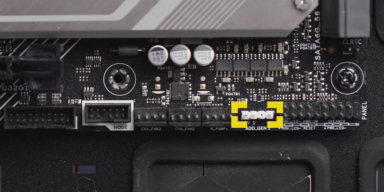
Do not interchange 5 V addressable and 12 V non-addressable connections. Also check limits on total LED count and power draw. Long chains can produce dimming or control problems.
Proprietary systems can simplify setup while adding cables and reducing cross-compatibility. Pick the ecosystem deliberately, or be prepared to research adapters.
Step 2: Prepare Your Workspace and Tools
Yes, we are only on step two. The shopping decisions were the hard part.
Clear a sturdy, well-lit desk or table with enough room to rotate the case and lay it on its side. Move food, drinks, and anything easily knocked over somewhere else. This is build time, not snack time.
Gather:
- A Phillips screwdriver, ideally with a long shaft and magnetic tip.
- A flashlight, including your phone’s light if necessary.
- Cable ties or reusable hook-and-loop straps.
- Flush cutters if using zip ties.
- Optional isopropyl alcohol and lint-free cleaning material, such as coffee filters.
- An optional microfiber cloth for fingerprints.
- The case, motherboard, and cooler manuals.
A protective desk pad helps prevent scratches. Custom cables are an optional aesthetic expense, not a performance upgrade.
Take Static Precautions Seriously
An antistatic wrist strap is particularly worthwhile in dry environments. It must connect to a proper ground. “Wireless antistatic” straps do not do that job.
One grounding method is to connect a properly earthed PSU to a grounded outlet, leave its power switch off, and clip the strap to exposed metal on its chassis. Do not use an adapter that defeats the protective earth connection. An antistatic mat also needs its ground lead connected correctly.
Without a strap, periodically touching the grounded PSU chassis is better than doing nothing, especially after moving around. Keep all component installation and cable changes unpowered.
Step 3: Install the CPU on the Motherboard
Unbox the motherboard and set it on its cardboard box. The box supports the board and raises it enough to fit a graphics card during a preliminary test.
Handle the CPU by its edges. Avoid exposed contacts and keep its protective clamshell for future transport, resale, or warranty service.
Inspect the Socket First
There are two important socket arrangements:
- LGA: The delicate contacts are in the motherboard socket.
- PGA: The pins are on the processor.
For LGA, open the retention mechanism according to the board’s instructions and inspect the socket before installing anything. Angling it toward a light helps reveal irregular rows. For PGA, inspect the CPU’s pins from multiple directions.
If a new component has bent contacts, stop and address the problem with the seller. Fine tools can sometimes straighten pins, but repeated bending can snap them. This is delicate repair work, not a normal installation step.
Install a Mainstream LGA Processor
- Release and lift the socket retention mechanism.
- Match the CPU’s triangle and alignment notches to the socket.
- Lower the processor gently into place without sliding it across the contacts.
- Confirm it is sitting flat.
- Close the retention frame and secure the lever.
The lever may feel stiff. That is not unusual when the CPU is correctly positioned. On sockets with a pop-off protective cover, save that cover in the motherboard box for future service or shipping.
Install a PGA Processor
- Raise the socket’s locking arm.
- Align the processor’s orientation marker with the socket.
- Let the CPU settle into place.
- Keep it level while closing the locking arm.
If a PGA CPU does not drop into the socket, do not push. Check alignment and pins, then try again. A few extra seconds now beats an afternoon of straightening an entire field of tiny metal regrets.
Workstation and Server Sockets
Large sockets need their own instructions. Do not extrapolate from a desktop socket because the mechanism looks vaguely familiar.
AMD SP3-style Threadripper and EPYC installations use a carrier frame and numbered retention screws. Slide the CPU’s carrier into its rails, seat and lower it as instructed, then tighten the screws in the marked order using the supplied torque-limiting tool.
Some Intel Xeon designs, such as LGA3647, attach the CPU to a plastic carrier on the cooler before the whole assembly is lowered onto the socket. Alignment markers and guide posts determine positioning.
On a dual-socket motherboard with only one CPU installed, the manual determines which socket to populate and which memory slots belong to it.
Step 4: Install the Memory
Install RAM before a large cooler makes access annoying.
The motherboard manual is the authority on slot population. Do not rely on colors or assume that a layout from your last build applies here.
A common four-slot dual-channel arrangement uses A2 and B2 for a two-module kit. These are often the farther slot in each channel, a layout that helps signal integrity on many boards. Two-slot boards and workstation platforms have their own rules.
A single large module can be a deliberate compromise when leaving space for a later upgrade, but it gives up the benefits of a fully populated channel configuration in the meantime.
- Open the slot’s movable latch or latches.
- Align the offset notch in the memory module with the slot’s key.
- Guide both ends into the slot.
- Press down evenly until the module seats and the latches lock.
- Check both ends rather than trusting one audible click.
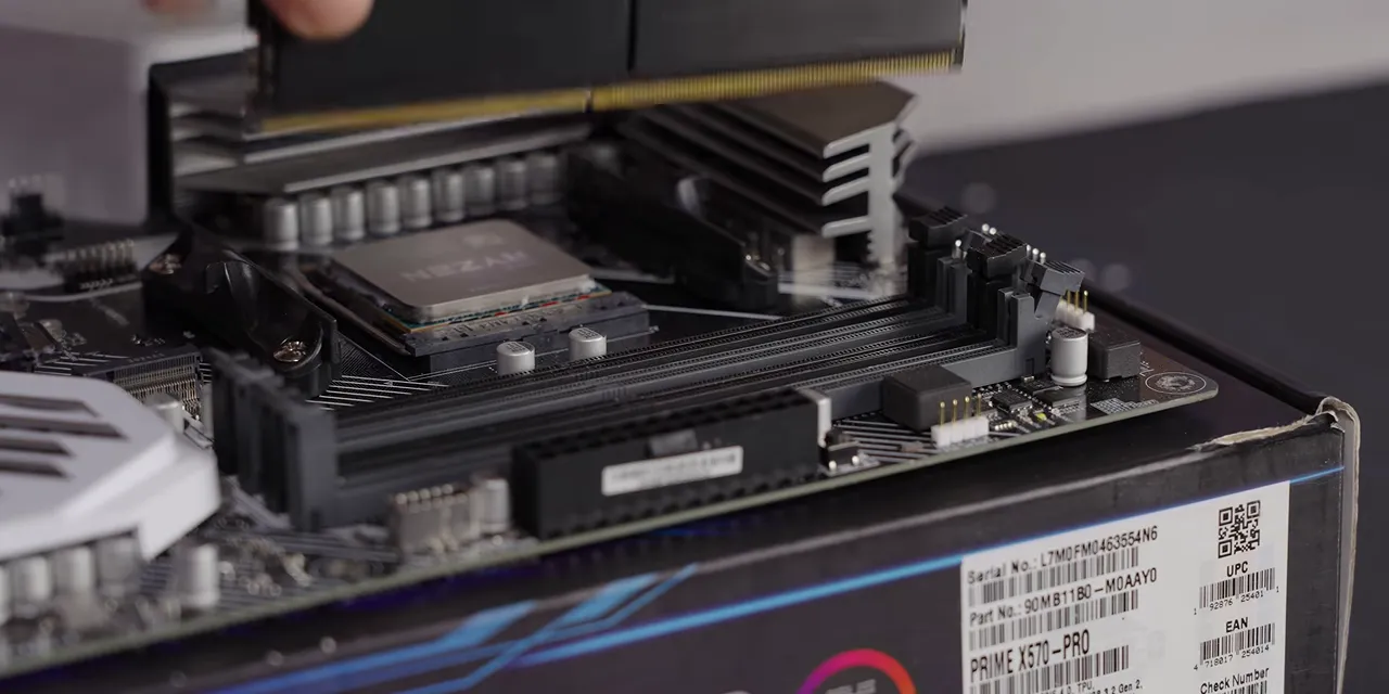
On boards with memory on both sides of the CPU, module orientation may reverse from one side to the other. Check the notch every time you change sides.
Step 5: Install the M.2 SSD
M.2 slots are often hidden beneath motherboard heatsinks. Find them in the manual and check the supported drive type.
When you have a choice, the CPU-connected slot is a good starting point for your fastest NVMe drive. Chipset-connected slots share platform resources and can face additional bandwidth constraints. If using SATA M.2 storage, choose a slot that explicitly supports it and consider leaving a faster CPU-connected slot available for later.
- Remove the motherboard’s M.2 heatsink, if present.
- Remove protective film from the heatsink’s thermal pad.
- Position the standoff for your drive’s length. A 2280 drive is 80 mm long.
- Align the drive’s connector notch with the slot.
- Insert it at roughly a 30-degree angle until fully seated.
- Lower it gently onto the standoff and secure it with the supplied screw or retention mechanism.
- Reinstall the compatible heatsink.
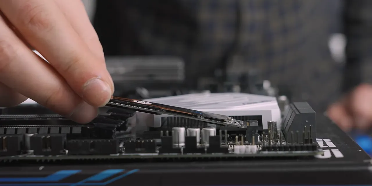
The tiny retaining screw needs to be snug, not brutally tight. Starting it with a slight counterclockwise turn until the threads align can help avoid cross-threading.
If the SSD has a factory heatsink, check the drive and motherboard instructions before deciding which heatsink to use. Do not try to stack incompatible cooling assemblies.
M.2 adapter cards use the same basic drive installation process. The adapter itself then installs into its designated motherboard connector or PCIe slot.
Step 6: Mount the CPU Cooler
Cooler installation varies enough that the included instructions are mandatory reading. The underlying pattern is usually a backplate, spacers, mounting hardware, thermal compound, and even tightening pressure.
Fit the Correct Mounting Hardware
Some coolers supply a backplate; others reuse the motherboard’s. Use the exact spacers, brackets, and mounting holes specified for your socket.
On AMD boards, some coolers require removing the factory plastic retention brackets, while clip-on models reuse them. Keep any removed parts. They may be needed for another cooler or when selling the board.
A tower cooler generally works best oriented to move air toward the rear exhaust. Confirm the mounting direction before tightening everything down.
Apply Thermal Compound
Pre-applied paste is normally fine. You do not need to remove it just to make the process more complicated.
If replacing it, clean the CPU heat spreader and cooler base with isopropyl alcohol and lint-free material, then let the surfaces dry.
The required amount depends on the heat spreader’s size. Traditional small desktop processors may need only a modest central application, while larger desktop and workstation chips require more. A line, central blob, or X can all work when the amount provides suitable coverage under mounting pressure.
Large Threadripper, EPYC, and Xeon heat spreaders need a correspondingly larger application, such as the manufacturer’s recommended multi-dot pattern or an appropriately sized X. Follow current instructions for the exact CPU and paste rather than applying one tiny dot to everything ever made.
Remove any protective sticker from the cooler’s contact plate. It is a surprisingly effective way to ruin your cooling performance while feeling very confident about your cable management.
Tighten Evenly and Connect the Fans
Start all mounting screws before fully tightening them. Alternate between opposite sides on two-screw mounts and use an X pattern on four-screw mounts. Tighten gradually and follow the manufacturer’s stopping or torque guidance.
Reattach air-cooler fans in the correct direction. Molded airflow arrows are useful; on conventional fans, the side with the stationary support struts is generally the exhaust side. Position cables toward the motherboard when practical.
Check RAM and heatsink clearance. You may need to raise a fan slightly or omit an optional second fan, provided the resulting cooler still fits the case and suits the CPU.
Connect the primary fan to CPU_FAN. Additional fans can use CPU_OPT or a suitable splitter. Respect the header’s current limit.
A liquid cooler may also need dedicated pump power, SATA or peripheral power, an RPM-sense connection, USB, and lighting connections. An RPM signal lets the system detect a failed pump or report a cooling fault. Follow the cooler’s wiring diagram.
For an AIO, installing the mounting hardware now and securing the radiator later is often easiest. You will still need the cooler properly connected for the preliminary test.
Step 7: Test the Core Components Before Installing Them in the Case
Finding a problem now is a good thing. It is much easier to troubleshoot a motherboard sitting on its box than one buried behind a radiator, a giant GPU, and your finest cable ties.
Use a properly installed, functioning CPU cooler for the test. For a custom loop, completing the cooling setup on the bench is the sensible approach.
Connect the Minimum Test System
- Install a graphics card if the system needs one for display output.
- Connect the motherboard’s 24-pin ATX power cable.
- Connect the required CPU EPS power cable or cables.
- Connect every required GPU power input.
- Attach a keyboard and display.
- Switch on the PSU.
The CPU’s eight-pin EPS connector and an eight-pin PCIe GPU connector are not interchangeable. Never force a power connector.
When using a dedicated graphics card, connect the display to that card, not automatically to the motherboard.
If the motherboard has no onboard power button, find the exact power-switch pins in the manual. Briefly bridging those two pins with the metal tip of a screwdriver performs the same function as the case’s power button. Do not randomly poke other headers.
Check the BIOS
Enter setup with the indicated key, commonly Delete. Confirm:
- The correct CPU is detected.
- All expected memory capacity appears.
- The M.2 storage devices appear.
- CPU fans and relevant pump signals are present.
- CPU temperature settles rather than continuing to climb.
Some processors run warmer in firmware setup than expected, so do not panic over one number without context. What matters is whether the cooling behaves appropriately. If temperatures keep climbing or the mount seems suspect, shut down, inspect contact and paste coverage, then reinstall the cooler.
If the Bench Test Fails
Start with the obvious things. They are obvious because they go wrong a lot.
- Power but no picture: Check the display connection and monitor input, GPU seating and power, and RAM seating.
- Memory-related failure: Try one module in the manual’s recommended slot, then add modules back individually.
- No response at all: Check the outlet, PSU switch, 24-pin cable, CPU power, and PSU-side modular connections.
- CPU or persistent memory faults: Recheck CPU support and BIOS requirements before considering a careful socket inspection or CPU reseat.
Diagnostic LEDs and hexadecimal POST codes can identify the stage where startup stops. Their meanings vary by motherboard. Read the labels and manual rather than assuming one vendor’s colors apply everywhere.
Some systems object when nothing is connected to CPU_FAN. Some motherboards require a particular BIOS revision to support a CPU even when the socket matches.
If the basics do not solve it, troubleshooting with known-good components can help isolate the problem. The build guide forum discussion is another place to seek more specific help.
Once the test succeeds, shut down, switch off and disconnect power, then remove the temporary connections and GPU before proceeding.
Step 8: Prepare the Case and Check Every Standoff
Protect the desk and case finish, remove the side panels, and put them somewhere safe. The original case box is a good option. Remove the accessory box from inside the chassis.
If the motherboard uses a separate rear I/O shield, install it now. Match its orientation to the motherboard ports, then press it securely into the case opening. Discovering it on the desk after the motherboard is screwed in is a classic experience. You do not need that experience.
Move loose case cables behind the motherboard tray so they cannot become trapped beneath the board.
Standoffs Prevent Shorts, Unless You Put Them in the Wrong Place
Standoffs hold the motherboard above the metal tray. Compare their positions with the board’s mounting holes.
- Add missing standoffs where the motherboard needs support.
- Remove every standoff that does not align with a motherboard mounting hole.
- Check beneath cosmetic covers and M.2 heatsinks for hidden mounting positions.
- Test-fit the board and confirm the mounting points align.
An extra standoff under the motherboard can short it or force it to bend. This is one of the most important checks in the entire build.
Secure standoffs appropriately without stripping the tray. A suitable socket tool can help, but inexpensive cases do not reward heroic tightening force.
Step 9: Install the Motherboard and Connect Front I/O
Before securing the board, consider connecting the CPU EPS cable if a large cooler will block access. With a modular PSU, you can attach the motherboard end and feed the other end through the upper cable-routing opening.
Lower the board into place, align the rear ports and standoffs, and start the screws loosely. A central locating peg or screw can help keep everything positioned while you fit the corners.
Use the case’s specified screws. Many systems use coarse 6-32 motherboard screws, while others use M3. Test gently rather than forcing the wrong thread. Once every screw is started, tighten them until secure without crushing the board.
Power Button, Reset Button, and LEDs
Connect the front-panel leads while access is still easy. Route them through the nearest useful opening and follow the motherboard’s header diagram exactly.
- Power switch and reset switch: Polarity does not matter. They simply close a circuit.
- Power LED and drive activity LED: Polarity matters. If an LED does not illuminate, its connector may need reversing.
- Optional speaker or buzzer: Useful for beep-code diagnostics on supported boards.
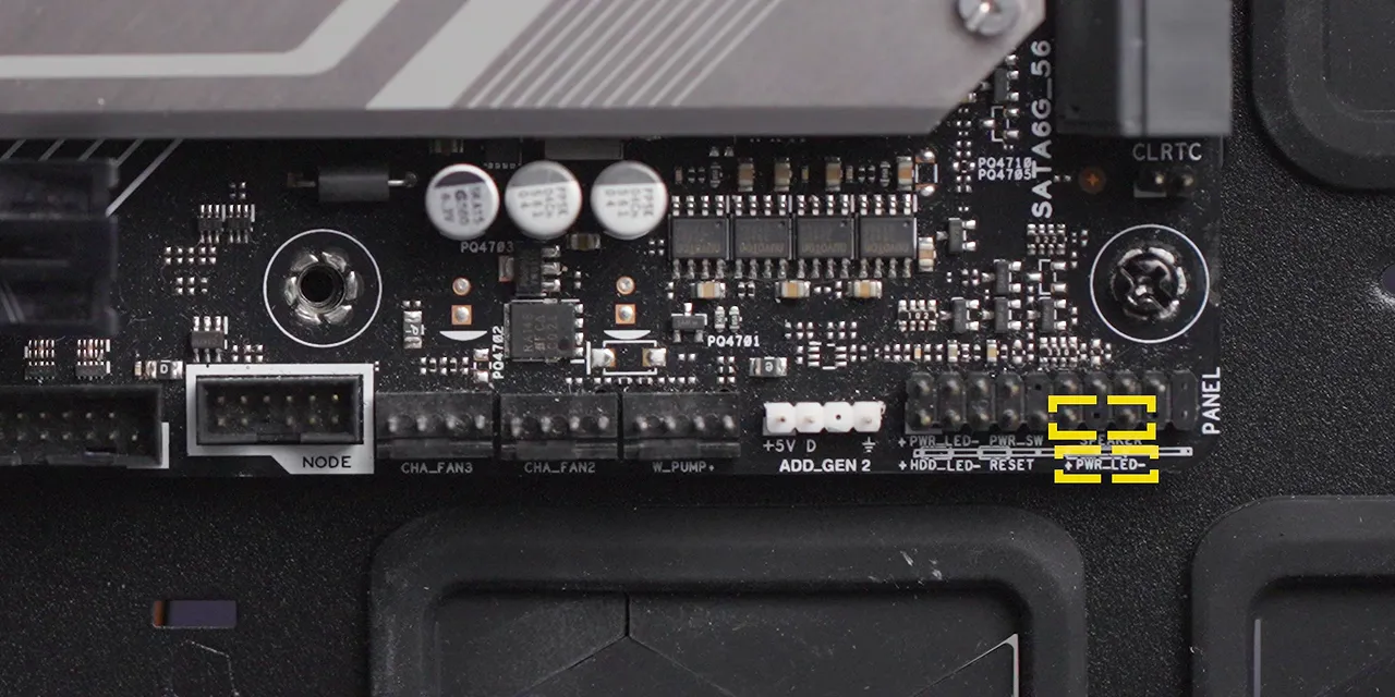
Header layouts vary. Do not use a generic diagram as permission to ignore the manual.
Front-Panel Audio
If the case offers both AC’97 and HD AUDIO plugs, use HD AUDIO on a compatible modern board. It supports functions such as jack sensing that the older interface lacks.
The audio header is often near the board’s lower-left edge. Align the blocked pin and make sure the connector covers both rows, not just one.
Front-Panel USB
Internal USB connections commonly include a USB 2.0 header, a larger USB 3.x header for front Type-A ports, and a compact internal connector often used for front USB-C.
Similar-looking headers are not necessarily compatible. Older FireWire headers may be labeled FW or 1394 and must not receive a USB plug. Serial headers may say COM, and parallel headers may say LPT.
USB 2.0 plugs are keyed by a missing pin. Check both rows before pressing them on. If you run out of internal USB 2.0 connections, compatible internal hubs are an option.
The large USB 3.x Type-A header deserves particular care. Its pins can make contact before the plug is fully aligned, and insertion requires enough force that a bent pin may not be obvious by feel. Visually align it before pressing straight in.
These cables are stiff. Route them gently and do not use cable ties to wrench the connector sideways. Front USB-C connectors can also rock loose if cable routing puts too much tension on them.
Step 10: Install SATA SSDs and Hard Drives
Cases commonly provide removable trays for 2.5-inch SSDs and 3.5-inch hard drives.
For a 2.5-inch drive, remove the tray, align the side or bottom mounting holes, and use the appropriate M3 screws. Reinstall the tray with the connectors accessible.
For a 3.5-inch hard drive, follow the tray’s screw or tool-free retention design. Rubber isolation grommets help reduce vibration. These drives commonly use coarse 6-32 screws, sometimes special long screws supplied with the case.
Older fixed cages may require sliding the drive into rails and securing it from both sides. Heavy mechanical drives need proper mounting. Do not treat them like a lightweight SSD with no moving parts.
Connect SATA Data
SATA data connectors have an L-shaped key. Line it up, push the cable in straight, and engage any locking clip. Press that clip when removing the cable later.
Route the other end to an enabled motherboard SATA port. Check the manual because some SATA connections share resources with M.2 or PCIe slots and may become unavailable when those are occupied.
Right-angle ends can suit drives in cages. Straight ends are often necessary for SSDs mounted flush behind the motherboard tray.
Avoid putting sideways tension on either connector. Breaking the plastic L-shaped tongue is not a fun way to discover how good your soldering skills are.
Step 11: Install Case Fans and Radiators
Plan a clear route for air to enter, pass over hot components, and leave. A common arrangement uses front and bottom intake with top and rear exhaust.
Balanced airflow or slightly positive pressure can work well. Positive pressure means intake airflow exceeds exhaust airflow, which helps limit unfiltered dust entry when the intakes are filtered. Fan count alone does not determine the result because fan speeds and restrictions matter.
Avoid arrangements that immediately exhaust fresh intake air before it reaches the components.
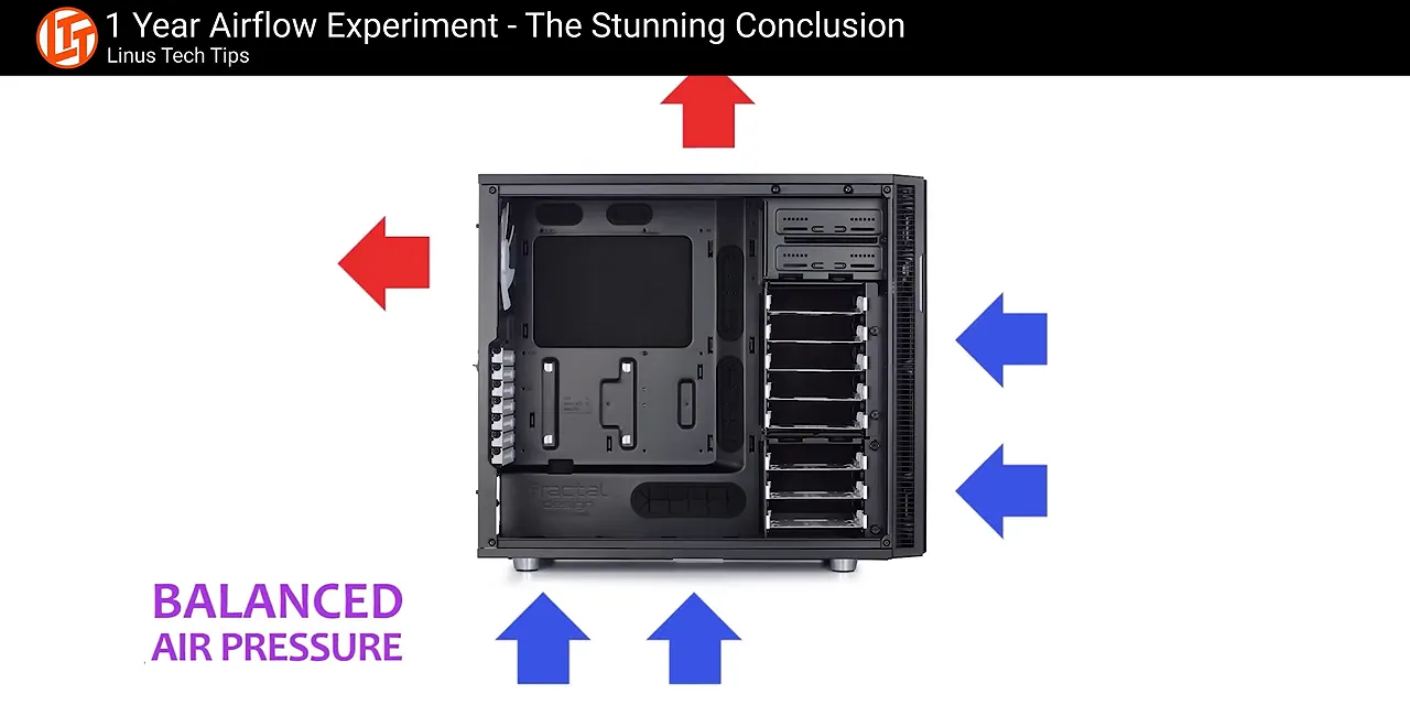
Install case fans using their supplied screws or rubber mounts. Start opposing corners before tightening everything, keep wires clear of blades, and orient the cable exit toward a useful routing point.
If tightening distorts the mount enough for blades to rub, ease the screws or use suitable spacers rather than leaving the fan scraping against the chassis.
Radiator Position and Maintenance
A radiator can often mount at the top as exhaust or at the front as intake. Space, component clearances, and the case layout may make the decision for you.
Push versus pull fan placement often matters more for maintenance than raw performance. A pull arrangement that leaves the dusty radiator face accessible can save future disassembly. Design for the cat hair you will have in two years, not just the photograph you want today.
For an AIO with a pump in the CPU block, do not make the pump the highest point in the loop. Give trapped air somewhere higher to collect in the radiator, and follow the manufacturer’s permitted mounting orientations.
A removable radiator bracket makes assembly much easier. Fit the fans and radiator outside the case when possible. Keep cables out of the mounting surfaces, and use the correct supplied screw lengths.
Reconnect the CPU block, pump, fans, USB, lighting, and any controller connections according to the cooler’s manual. If the AIO has an integrated fan controller, using it can let its software coordinate the pump and radiator fans.
Power and Control the Fans
Connect case fans directly to motherboard headers, through appropriate splitters, or through a compatible powered hub. Mount controllers where connections are accessible without blocking cable openings.
Respect header current limits. A splitter provides more plugs; it does not magically increase the amount of power a header can deliver.
Temporarily tuck excess fan and RGB wiring behind the motherboard tray. Final tidying comes later.
Step 12: Install the Power Supply and Finish Power Wiring
Disconnect the PSU from the wall before mounting it.
If the case has a filtered bottom intake, the PSU fan commonly faces downward to draw its own fresh air. Without an intake beneath it, face the fan into an available air path instead. The fan needs to breathe.
On a modular PSU, connect the required cables before sliding it into a cramped compartment. Use only the cables intended for that exact model.
- Attach the removable PSU mounting plate, if the case uses one.
- Feed cables through and slide the PSU into position.
- Secure it through the proper threaded mounting holes.
- Connect the CPU EPS leads.
- Route and connect the motherboard’s 24-pin ATX lead.
- Connect SATA or other peripheral power to drives, hubs, and controllers.
- Leave the GPU power leads accessible for the next step.
Do not accidentally screw into the ventilation grille. It can look convincing while accomplishing absolutely nothing useful.
The 24-pin plug may be a 20+4 design, and CPU power may split into 4+4. Make sure every section sits flush and the latch engages.
SATA power uses a wider L-shaped connector than SATA data. Align it carefully and verify it is seated straight. Older four-pin peripheral connectors can be stiff, and poorly retained pins sometimes push backward; inspect rather than forcing them.
Some PSUs offer hybrid or semi-passive fan operation. The switch behavior varies, so use the PSU manual to select the intended mode instead of assuming that “in” or “out” always means the same thing.
Step 13: Install the Graphics Card and Other Expansion Cards
The top full-length PCIe slot is usually the preferred GPU slot because it commonly connects directly to the CPU. Confirm that in the motherboard manual.
- Remove the case slot covers corresponding to the card’s position and thickness.
- Open the PCIe slot’s retention latch.
- Remove any protective cover from the card’s edge connector.
- Align the card with the slot and rear case openings.
- Press it straight into place until fully seated and latched.
- Secure its rear bracket to the case.
- Install a support bracket if needed.
- Connect every required GPU power input.
On inexpensive cases with breakaway slot covers, work carefully. Gently fatigue the metal rather than wrenching it around near the motherboard. Sharp case metal has collected enough blood already.
Large graphics cards can sag. A correctly adjusted support bracket helps keep the card level and reduces strain, especially if the PC will move.
The same basic installation method applies to other PCIe expansion cards.
For GPU power, use the required cable configuration. Dedicated PCIe cables are preferable where specified or available; daisy-chain connectors are not automatically defective, but the GPU and PSU instructions take priority. With 6+2-pin plugs, couple the pieces correctly so all eight pins seat flush.
Do not confuse GPU power with CPU EPS power, and do not leave required inputs unconnected.
Step 14: Finish Cable Management
If you have been routing cables as you go, this is tidying rather than excavation.
The ideal is a main cable bundle with smaller branches leaving where needed. Real cable lengths make that imperfect, and that is fine.
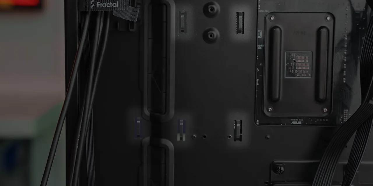
- Use the case’s routing channels and tie-down loops.
- Bundle related cables without crushing them.
- Leave enough slack that plugs are not pulled sideways.
- Keep wiring clear of fans and panel edges.
- Trim zip ties cleanly with flush cutters.
- Confirm the rear panel fits without being forced against a mountain of cables.
Custom-length cables can make the result prettier, but a reliable, serviceable build does not need to be an art installation.
Step 15: Power On and Troubleshoot Methodically
Connect the monitor and keyboard, check the PSU and outlet switches, and press the case power button.
If it works, excellent. If it does not, resist the urge to declare the entire computer dead.
No Power at All
Check the outlet, PSU switch, front-panel power-switch connection, and power cables. Reseat the 24-pin and CPU EPS plugs with power disconnected, including the PSU ends on a modular unit.
If the board receives standby power but will not start, check for a short. Extra motherboard standoffs and stray metallic objects are prime suspects.
Power but No Display
Verify that the monitor is connected to the intended graphics output. Then check GPU power and seating, followed by RAM seating.
Try a minimal memory configuration, interpret the motherboard’s diagnostic LEDs or POST display, and confirm CPU compatibility with the installed BIOS.
POST codes are board-specific. A code such as 00 can be a reason to investigate CPU initialization on some boards, but it is not a universal diagnosis.
Missing Memory, Storage, or Unreasonable Temperatures
Once you reach UEFI setup, check these in order:
- CPU temperature and cooling behavior.
- Total detected RAM.
- Detected storage devices.
Power down before reseating anything. Missing RAM can occasionally trace back to CPU seating or socket contact rather than the module itself. Missing storage may come from an incompatible M.2 slot or a disabled shared SATA port.
Configure the BIOS and Boot Your Operating System
A successful POST means the hardware can initialize. It does not necessarily mean every setting is where you want it.
Enable the Appropriate Memory Profile
Your RAM may initially run at conservative defaults rather than the settings printed on its packaging. On the platforms covered here, enabling XMP or DOCP loads the kit’s intended frequency and timings.
These profiles can involve overclocking, so compatibility and stability still matter. ECC-oriented builds generally call for a different approach focused on supported operating settings.
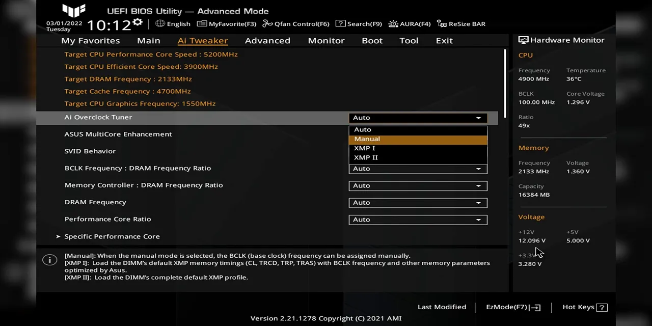
Understand Automatic CPU Enhancement
Settings such as multicore enhancement can increase performance at the expense of heat and power consumption. Disabled is the stock choice for this type of enhancement. A substantial cooler may give you room to experiment, but leaving it off is perfectly valid.
Most other settings can remain at their defaults unless you have a reason to change them.
Prepare for Windows 11 or Your Chosen OS
For a Windows 11 configuration, check TPM and Secure Boot settings and disable the Compatibility Support Module, or CSM, as appropriate for a UEFI installation. The names and menu locations vary by board. Microsoft’s Windows 11 requirements provide a useful reference alongside the motherboard documentation.
Insert your operating system installer USB drive. If it does not start automatically, use the motherboard’s boot menu, often reached with a key such as F8 or F12, and select the installer.
If the USB device does not appear, recheck firmware USB settings. On some boards, a disabled legacy USB support option can interfere with detection, although normally you should not need to change it.
At this point, the hardware build is complete and the machine is ready for operating system installation.
The real accomplishment is not just getting one particular collection of parts to turn on. It is understanding the pattern: choose for the workload, verify compatibility, build in an order that preserves access, test early, and troubleshoot one thing at a time. That is the part you get to keep when all the components change.
Seasonic sponsored this guide. For information about the featured power supply, see the Seasonic TX 1000.


