All your parts have arrived. You have a screwdriver, a clear spot on the table, and just enough confidence to open the CPU packaging. Then the doubt sets in. Which way does this go? How hard am I supposed to push? Was that noise expensive?
Building your first PC is full of perfectly reasonable questions. The trick is knowing which parts need a firm push, which parts should drop into place, and when to stop and check what you are doing.
For this build, my son is doing the assembly for a friend with a hard limit of $800 Canadian, roughly $550 US. The friend already has a PS5. The goal is access to PC games, including Minecraft, and keyboard-and-mouse Roblox, not an unlimited-budget benchmark monster. Used parts make that possible, although one of ours gives us a very memorable troubleshooting session.
What You'll Learn
- Used AM4 components can leave room for a capable graphics card on a tight budget.
- Installing the CPU, RAM, and cooler outside the case makes assembly easier.
- Connector labels, alignment notches, and motherboard documentation matter more than guessing what fits.
- A system reaching the BIOS can still have faulty hardware that requires further testing.
Table of Contents
- Choose Parts for the Job, Not the Spec Sheet
- Build Up the Motherboard Outside the Case
- Thermal Paste and the CPU Cooler
- Prepare the Case Before Installing the Motherboard
- Save Money on PSU Features, Not Basic Quality
- Connect the Cables Without Turning Them into Spaghetti
- Install the SSD, Even If the Used Case Is Missing Something
- Install the RTX 3060 Ti and Its Power Connector
- Finish Cable Management and Check Panel Clearance
- First Boot: Enable the Memory Profile, Then Test
- What Did $550 Actually Get Us?
- Sponsor: Centralized Storage with UGREEN
Choose Parts for the Job, Not the Spec Sheet
At this budget, buying everything new makes it difficult to get the same gaming value. We chose an older AM4 platform so we could use cheaper DDR4 memory and leave enough money for a capable graphics card.
Here is the hardware we assembled:
- CPU: AMD Ryzen 7 3800X initially, replaced with a Ryzen 7 3700X after diagnosing a faulty processor.
- Motherboard: Gigabyte B550 Gaming X V2.
- Memory: 16GB Corsair Vengeance LPX DDR4-3200, using two 8GB sticks.
- Graphics card: EVGA GeForce RTX 3060 Ti XC Gaming.
- Storage: Kingston A400 960GB SATA SSD.
- Power supply: MSI MAG A550BN, a 550W, 80 PLUS Bronze, non-modular unit.
- Case: Gamer Ninja Eraser ATX mid tower.
- Cooling: An AM4-compatible air cooler with thermal compound.
Both of those Ryzen processors have eight cores and use AMD’s Zen 2 architecture. They are older, but still entirely reasonable choices for the games this machine is intended to run.
Would I have liked 32GB of RAM? Absolutely. But 16GB was the compromise that fit this budget. Running a two-stick kit at 3200 megatransfers per second gives us a sensible pairing for this platform without spending money we do not have.
The same logic applies to the motherboard. A higher-end chipset would not automatically make this PC faster. It could provide more connectivity, such as additional M.2 slots or high-speed USB ports. Our B550 board has two M.2 slots and enough expansion for this entry-level system. That is what matters.
Not sure whether your shopping list is complete? Cheat.
Find an existing, compatible parts list and use it as a checklist. You do not have to invent PC building from scratch.
Check off the CPU, motherboard, memory, storage, graphics card, power supply, case, and cooler. Remember thermal compound, too. A parts-list tool such as PCPartPicker can help organize the build, but still check the motherboard documentation and physical clearances, especially with secondhand hardware.
Our final price is an example of what we found, not a promise that the same used components will cost the same amount everywhere.
Build Up the Motherboard Outside the Case
You can install the motherboard in the case first and add components afterward. It is just less convenient. Working outside the case gives you better access to the CPU socket, RAM slots, and cooler mounting hardware, rather than making you reach around sheet metal.
Install the AM4 processor without touching the pins
Handle the CPU by its edges. The pins are gold-plated and relatively non-reactive, but skin oils and debris do not improve an electrical connection. Neither does bending a pin.
A poor connection can cause surprisingly specific problems. A system might lose access to a memory slot or PCI Express connectivity rather than simply refusing to start. That is a lot of troubleshooting you can avoid by keeping your fingers off the contacts.
- Find the small triangle marking on one corner of the processor.
- Find the matching orientation mark on the motherboard socket.
- Lift the socket’s retention arm before inserting the CPU.
- Align the markings and gently lower the processor into place.
- Once it is sitting flat, lower the retention arm to secure it.
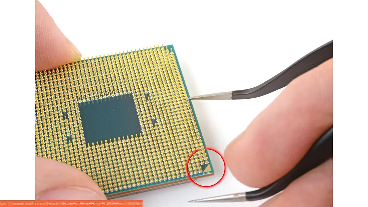
The CPU itself should not need to be forced into the socket. If it is not sitting properly, stop and check the orientation.
Put the RAM in the correct slots
For this two-stick configuration, use A2 and B2, the second and fourth memory slots away from the CPU. Check your own motherboard manual rather than assuming every board has the same preferred arrangement.
Open the applicable retaining clips, then line up the notch in the RAM’s contact edge with the key in the slot. The sticker is not a reliable orientation guide. We briefly tried that approach. The notch won.
Once the module is correctly aligned, press firmly and evenly until it is fully seated and the retaining clips engage. RAM can take more pressure than a first-time builder expects. That does not mean you should force a misaligned stick into place.
Thermal Paste and the CPU Cooler
Before installing the cooler, make sure you have thermal compound. Remove the cap from the syringe. Yes, that is technically a step worth mentioning.
Apply the compound around the center of the CPU’s heat spreader rather than trying to decorate every edge. The cooler’s mounting pressure spreads it across the contact area.
Our application was not exactly a work of art, so we checked it: place the heatsink on the CPU, apply a little pressure, then lift it to inspect the spread. We had sufficient coverage for the final mounting pressure to finish the job. You do not need to repeatedly remove the cooler just to admire your paste.
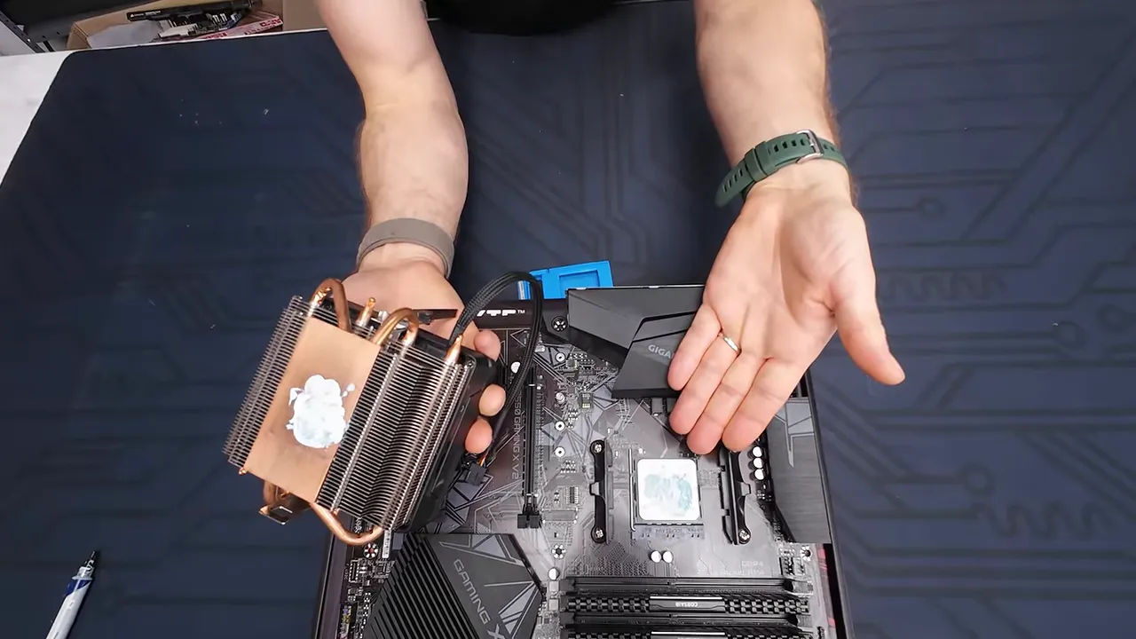
Our cooler uses the AM4 clip-and-lever mounting system. Hook the retaining clips onto the mounting tabs, then close the locking lever. Getting the second clip into place can require tilting the cooler and leaving the lever open until both sides are caught.
It can feel alarmingly stiff the first time. Check that the hooks are engaged correctly before applying the pressure needed to close the lever.
Use the CPU fan header
Connect the cooler’s fan to the motherboard header labeled CPU_FAN, normally near the processor socket.
Other compatible fan headers may physically accept the plug, but CPU_FAN is the sensible default. The motherboard is configured to control that fan according to CPU temperature.
This is also a good time to tuck away the fan cable. Cable management is easier when you think about it throughout the build rather than discovering at the end that every wire has chosen a different scenic route.
Prepare the Case Before Installing the Motherboard
We did not have much money left for the case, so we used a very inexpensive one. It worked, but it also demonstrated why nicer cases can be worth paying for.
Remove the side panels before you start installing parts. Opening the case up gives you room to work and lets you inspect the mounting points, cable-routing holes, and any parts that might get in the way.
Our first attempt to lower the motherboard into place revealed an interference problem between the rear fan and the motherboard’s rear I/O area. The solution was to remove the fan and reassess its fit afterward, not push harder and hope.
Handle the motherboard by its edges or sturdy features such as heatsinks and the I/O cover. Avoid grabbing exposed components or smearing your fingers across the circuit board.
- Check that the case’s motherboard standoffs correspond to the board’s mounting holes.
- Move loose cables out of the way.
- Guide the rear I/O into its opening while lowering the board onto the standoffs.
- Check alignment before installing the mounting screws.
Can the motherboard’s screw holes wear out?
The mounting holes have designated clearance areas around them. Ordinary installation marks there are not the same as damaging a signal trace elsewhere on the board.
That does not make the motherboard a suitable woodworking project. Do not drill new holes in a PCB. The board contains electrical connections within its layers, and a random hole can destroy it. Use the intended mounting locations without overtightening the screws.
Save Money on PSU Features, Not Basic Quality
The power supply is tempting to cheap out on because a more expensive one does not produce more frames per second. You still do not want to underspend here.
For this system, we chose a reputable-brand 550W power supply with an 80 PLUS Bronze efficiency certification. That capacity is enough for our selected components. The efficiency badge is one specification, not a substitute for evaluating the actual PSU model.
Our cost-saving compromise was non-modular cabling. All the cables are permanently attached, including the ones we do not need. That creates more work behind the motherboard tray, but saves money without requiring us to buy a higher-end feature set.
Before fastening everything down, look at the cable-routing openings. We discovered one potentially cleaner route only after the PSU blocked easy access to it. My son declined the opportunity to remove the power supply and redo the work. Apparently, friendship has limits.
Connect the Cables Without Turning Them into Spaghetti
The small connectors are often the most tedious part of a PC build. Take them one at a time, untangle each cable, and route it near its destination before plugging it in.
Many connectors are keyed, but “it fits” is not a complete wiring strategy. Use the labels and motherboard manual to identify the correct header.
- Motherboard and CPU power: Make sure the board’s required power connections are installed.
- Front USB: Match each case USB cable to the appropriate motherboard header.
- Front audio: Connect the HD AUDIO plug to the board’s front audio header.
- Case switches and lights: Follow the front-panel header diagram.
- Storage and graphics power: Leave suitable cables routed toward the SSD and GPU.
Is it okay to bend cables?
Some bending is unavoidable, but avoid sharp bends or excessive strain at a connector. Be especially careful with the front USB header and its pins. A bent pin can be an annoying repair, assuming it can be repaired at all.
Line the connector up before pushing it into place. Do not use the cable as a handle to wrench the plug sideways.
Do front-panel connectors have a direction?
LED polarity matters. The positive lead for the power LED needs to connect to the positive pin. Use the board markings or manual to identify it rather than relying on a guess about which side is positive.
The case’s power and reset switches are different from LEDs: their switch connections do not depend on polarity. They still need to go on the correct pair of pins.
If the individual front-panel plugs are awkward to reach, needle-nose pliers can help hold them together while you guide them onto the header. Gently. These are little plastic connectors, not something that needs crushing into submission.
A few cable-routing habits help enormously
- Run cables through the opening nearest their destination where practical.
- When cables cross, put the ones traveling farther underneath the shorter runs.
- Use the loops behind the motherboard tray as zip-tie anchors.
- Leave final tightening until the components and their cables are installed.
Install the SSD, Even If the Used Case Is Missing Something
The SSD is the storage device. Its NAND flash holds the operating system, applications, and games. In our case, that is a 960GB Kingston SATA drive.
Modern M.2 NVMe drives can provide higher speeds and eliminate the separate data and power cables required by a 2.5-inch SATA SSD. But on the secondhand market we were shopping, the SATA drive was a useful way to get more storage within budget.
There was just one small problem: our used case was missing its SSD mounting cage.
Missing accessories are one of the joys of secondhand hardware. Fortunately, a SATA SSD has no spinning platters or motor. It does not have the same mechanical mounting concerns as a hard drive, so we could secure it with double-sided tape in a suitable location.
That does not make SSDs indestructible. Secure the drive and avoid putting strain on its connectors.
A SATA SSD needs two separate connections:
- SATA power from the power supply.
- SATA data between the drive and a SATA port on the motherboard.
We also connected the case’s lighting power lead while sorting out the remaining power cables. After that, the GPU was the last major component standing between us and final cable management.
Install the RTX 3060 Ti and Its Power Connector
Graphics cards have become painfully expensive, but patience can still turn up useful secondhand deals. We found RTX 3060 Ti options that kept the whole build around $550 to $575 US. That is the system budget, not the price of the graphics card alone.
The RTX 3060 Ti gives this machine solid gaming capability and access to features such as DLSS upscaling. It is not a latest-generation flagship, and it does not need to be.
- Identify the motherboard’s intended graphics-card slot.
- Check which rear expansion-slot covers line up with that slot and the card’s bracket.
- Remove the correct covers.
- Open the PCIe slot’s retention latch.
- Align the card and press it into the slot until it is fully seated.
- Secure the card’s bracket to the case.
- Connect the required PCIe power cable.
We removed the wrong slot covers on the first attempt. Annoying? Yes. Catastrophic? No. Release the PCIe latch before removing the card, correct the mistake, and try again.
How the 6+2-pin power plug works
Many PCIe power cables have a six-pin section with two additional pins that sit alongside it. This lets the connector accommodate graphics cards with either six-pin or eight-pin sockets.
For an eight-pin socket, align the two-pin section with the six-pin section so their small locating features hold them together, then insert the assembled plug. Make sure the whole connector seats properly.
Is the graphics card supposed to sag?
The familiar expansion-card mounting arrangement was not designed around today’s large, heavy GPU coolers. Some movement at the far end of a card is not surprising.
A support bracket can hold that end level. Our card was not so heavy that we expected it to break just sitting in the case, but transport changes the situation. Remove a heavy graphics card before shipping the PC rather than letting it bounce around while hanging from the slot and rear bracket.
Finish Cable Management and Check Panel Clearance
With all the cables connected, gather the excess behind the motherboard tray and secure it with zip ties. Even a modest effort makes the build much neater.
If threading a zip tie through an awkward anchor loop is difficult, bend the tip into a small hook first. That can help you guide it through and catch it from the other side.
Bundle cables sensibly, keep them clear of fans, and check the side panel before calling the job finished. We remembered that last check rather late. A tidy-looking bundle is not much use if it occupies the same space as the panel.
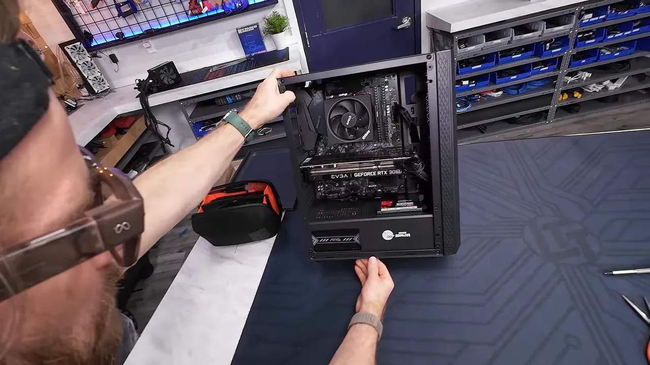
If the panel will not close without substantial pressure, redistribute the cables rather than crushing them. Budget cases do not always provide much room behind the motherboard tray.
First Boot: Enable the Memory Profile, Then Test
Once the system starts and you can enter the BIOS, configure the memory profile so the RAM runs at its intended speed. On this board, we adjusted the XMP setting for DDR4-3200, then pressed F10 to save.
Getting into the BIOS is encouraging. It is not proof that everything is healthy.
Our system would not boot Windows successfully. The storage initially looked suspicious enough that we asked for another bootable SSD. After further troubleshooting, though, the culprit turned out to be neither the motherboard nor the RAM.
It was the CPU.
The Ryzen 7 3800X was faulty. Replacing it with a Ryzen 7 3700X got the system working properly.
CPUs are not usually the first component I expect to fail, which made this a particularly irritating surprise. It is also a useful lesson: a successful BIOS screen does not eliminate every hardware fault, and the component that looks guilty first is not necessarily responsible.
With used hardware, leave time for testing. If you hit a problem, check your assembly and connections before assuming you broke something, then work through the diagnosis methodically. Buying secondhand can deliver excellent value, but it can also include someone else’s problem.
What Did $550 Actually Get Us?
After replacing the CPU, we had a genuinely capable little gaming machine for about $800 Canadian or $550 US.
The initial demanding game test was playable, even if the image was not the sharpest. During that testing, temperatures were around 72°C on the CPU and 70°C on the GPU, which was very reasonable for this configuration.
In Clair Obscur, we used 1080p output, DLSS Quality, and roughly medium-to-high settings, and the game ran well. A later Minecraft test reached around 200 frames per second. Those are different workloads, not a claim that every game runs at 200 FPS.
For a friend who wanted PC gaming alongside a PS5, that is a good result. We put money into the components that mattered, accepted a basic case and extra cabling, and dealt with a faulty used part along the way.
You do not need to know everything before your first build. You do need to check alignment, read the labels, ask questions, and resist the urge to solve every fit problem with more force. Well, except properly aligned RAM. That one really can need a firm push.
Sponsor: Centralized Storage with UGREEN
UGREEN sponsored this build. Its NASync DXP2800 GT is designed as centralized storage for family photos, movies, backups, and security footage, with two SATA drive bays and two M.2 SSD slots.
The promoted features include 10-gigabit networking, slide-out drive trays, and support for compatible ONVIF IP cameras for live feeds, local recording, playback, and event monitoring. It is a separate storage project from our budget gaming PC, but a relevant option if you want to keep household files and camera recordings in one place without an ongoing storage subscription.


